
Amplifier—amplification principle
1. Threaded expander
Threaded expander can be divided into two types: threaded expander plate and threaded expander roller.
(1) Threaded amplifier plate: As shown in Figure 2-16, the threaded amplifier plate is an amplifier with a simple structure. On the steel or copper plate, there are inclined grooves (threads) oriented from the center to the left and right. The angle between the chute and the plate axis is 10° to 15°. The expansion board is usually fixed on the frame. When the fabric slides over it, the expansion board will expand the fabric.

In analysis When looking at the expansion mechanism, a pair of threads with the centerline as the axis of symmetry can be taken to analyze their stress conditions, as shown in Figure 2-17. Since the fabric itself is flexible, when it passes through the threaded expansion plate in the v direction under the action of warp tension T2 >T1, the fabric in contact with the thread Embed in the thread and closely contact the thread slope H. As a result, the fabric is affected by the reaction force Q on the H surface.
The Q force is perpendicular to the H surface, and Q is decomposed into two components Qy and Qx along the warp and weft directions of the fabric. The Qx component forces the fabric to stretch along the weft direction, producing an expansion effect. In contrast, in Figure 2-17, if the fabric were to run in the opposite direction, the fabric would be on the opposite side of the thread x which would cause the fabric to shrink in the weft direction.
H′ is tight. Affected by the reaction force Q’ of the H’ surface, its weft component Q’ therefore depends on the expansion effect of the thread expansion board and the thread elevation angle of the expansion board, the warp tension of the fabric, the running speed, and the strength of the same board surface. The degree of contact is related to factors such as the nature of the fabric.
(2) Threaded expanding roller: The threaded expanding roller is a straight roller with a zigzag axial cross-section and left and right helical threads from the middle of the roller surface to both ends. Generally made of hard rubber, copper or stainless steel, as shown in Figure 2-18.

According to the In leisure conditions, thread expanding rollers can be divided into two types: active thread expanding rollers and passive thread expanding rollers. The expansion principles of the active thread expansion roller and the thread expansion plate are the same. Just because its rotation direction is opposite to the running direction of the fabric, it increases the relative speed between the fabric and the roller surface, thereby enhancing the expansion effect.
The passive thread expansion roller is dragged by the static friction between the fabric and the roller surface when it is running. Assume that the fabric shrinks in the weft direction under the action of warp tension, so that the fabric is close to the outer side of the thread, then the fabric will be affected by the normal supporting force Q on the side of the thread, as shown in Figure 2-19. Decompose Q into Qx and Qy, Qx is the amplification force on the fabric.
2. Bending roller expander

Roller bending expander generally consists of 1 to 5 bending rollers. In actual production, the three-bending roller expander is commonly used. The main component of the bending roller expander is the bending roller, and its structure is shown in Figure 2-20. From the appearance, the bending roller is a complete and elastic arc-shaped rubber roller that can rotate around its arc-shaped axis driven by the fabric. From the internal structure of the bending roller, it consists of two parts: the roller core and the roller body. The middle part of the roller core is an arc-shaped mandrel, on which a multi-section cylindrical sleeve is installed through a rolling bearing. The adjacent sleeves are connected in sequence by the sleeve teeth on their respective end faces. The mandrel is covered with a multi-section bakelite or cast iron bushing and is fixed on the mandrel with a key to prevent the mandrel from being worn. The entire roller core is covered in a rubber sleeve. In this way, on the one hand, it can prevent the bearing oil leakage of the roller core and the accumulation of dirt at the joint of the multi-section sleeve; on the other hand, it can increase the friction between the roller surface and the fabric and improve the expansion capacity.

Roller bending The principle of width expansion is that when the fabric is close to the surface of the bending roller with a certain pressure and runs in the direction shown in Figure 2-21, due to the static friction between the fabric and the roller surface, the weft amplitude of the fabric changes with the When the busbar of the bending roller moves from the AB position to the CD position, the busbar of the bending roller increases. Therefore, the width of the fabric in the weft direction also increases, that is, an expansion effect is produced.
The installation position of the bending roller directly affects its expansion effect. First of all, the arc direction of the bending roller must be consistent with the running direction of the fabric in order to expand the width. Otherwise, the fabric will shrink in the weft direction. Secondly, the larger the wrapping angle between the fabric and the bending roller, the greater the expansion capacity. However, the wrapping angle cannot be greater than 180°, otherwise, the weft direction of the fabric will shrink and wrinkle. Thirdly, the lead-in angle φ to the fabric must be larger than the lead-out angle φ, see Figure 2-22(a) and Figure 2-22(b). This can prevent the edge of the fabric from loosening contact with the bending roller, thereby enhancing the expansion force. This must be paid attention to when installing the front and rear cloth guide rollers of the bending roller. In addition, when the middle part of the bending roller tilts downward, it can make φ>φ, see Figure 2-22(c), and the expansion force increases. Therefore, by appropriately changing the installation position of the bending roll mandrel, the expansion capacity of the roll bending expander can be adjusted.

From theory It is said that the expansion capacity of the bending roller is directly proportional to the diameter of the bending roller and inversely proportional to the arc radius of the bending roller mandrel. Therefore, increasing the bending rollerThe diameter and reducing the radius of the mandrel can improve the expansion capacity of the bending roller. But in fact, too large diameter and too small arc radius will bring difficulties to the manufacturing of bending rollers. On the other hand, if the arc radius is too small, the warp yarns of the fabric will have severe middle and thin edges and dense defects, and a large forward convex arc-shaped weft bend will appear. The diameter of the domestic standard series bending roller is 100mm, and the arc radius of the mandrel is 7500mm.
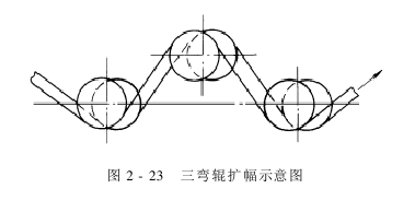
Three Bends The roller expander device, as shown in Figure 2-23, generally consists of three identical bent rollers. The expansion amount of the expander is the sum of the expansion amounts of the three bending rollers. In actual use, the relative position of the two bending rollers below can be changed or the bending roller can be rotated to change the position of its core axis to adjust the expansion capacity of the entire amplifier.
AAAMHGCVVBEW
Extendedreading:https://www.alltextile.cn/product/product-61-527.html
Extendedreading:
Extendedreading:
Extendedreading:
Extendedreading:
Extendedreading:
Extendedreading:
ExtendedReading:
Extendedreading:
Extendedread